🖨️ Comic book (halftone) shader
Making a halftone print shading effect in Unity.
4 minute read
Jump to heading Introduction
A while ago, I made a shader for a project of mine to simulate halftone shading. This note quickly explains how I created the effect.
Jump to heading Creating a dots pattern
To start, I created a Dots Pattern subgraph to create the actual grid of dots. This subgraph contains the following nodes.
The dots pattern is created using a Voronoi node. The UVs are rotated using the Rotate node. I then influence the cell density using some Gradient Noise together with a Scale property. Then finally I use the Dot Size property to decided how large the dots are by using the Step node.
The subgraph takes takes in the following parameters.
- UVs
- Dot Size
- Scale (how many dots there are)
- Randomness (to add noise to the pattern)
- Noise scale (for the shape of the dots)
- Noise strength (for the shape of the dots)
- Rotation (in degrees)
All these settings allow for creating a dynamic and configurable dots pattern.
Jump to heading Converting RGB to CMYK
The next step is to take an input image and convert the RGB color values to CMYK values (Cyan, Magenta, Yellow, Black). We use these 4 colors because a printer uses these colors as ink to generate an image. To perform the RGB -> CMYK conversion, I used a Custom Function node with the following code. The outputs are saturated to ensure an output between 0 and 1.
void RGBtoCMYK_float(float3 rgb, out float4 cmyk)
{
    float k = 1.0 - max(rgb.r, max(rgb.g, rgb.b));
    float c = (1.0 - rgb.r - k) / (1.0 - k);
    float m = (1.0 - rgb.g - k) / (1.0 - k);
    float y = (1.0 - rgb.b - k) / (1.0 - k);
    cmyk = float4(saturate(c), saturate(m), saturate(y), saturate(k));
}
I then take the CMYK outputs of this subgraph and multiply them with a Dot Size property before connecting them to the dot size input of the dots pattern subgraph I created earlier. The reasoning is that the higher the value of the CMYK output is, the bigger the size of the dot should be.
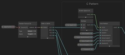
The image above does not show it, but the graph just has the same set of nodes for M, Y and K similarly to what is shown in the image for C. This way we end up with 4 different patterns, one for each color (CMYK).
Jump to heading Combining the patterns
Finally, I combine the 4 different dot patterns I created using Blend nodes. For the first blend, I use a background color property as the base. For this I usually just use white. I then use each of the 4 print colors (Cyan Magenta, Yellow and Black) as the blend values, each time using the appropriate dot pattern as the opacity input.
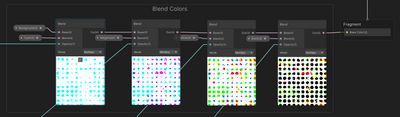
This way, all of the colored dot patterns get overlayed on top of each other. Finally we just output the result to the main color output of the graph.
Jump to heading Rotating the patterns
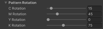
Remember that the dots pattern subgraph has a rotation input to rotate the pattern. I have created 4 rotation properties in total, one for each print color (CMYK) so that I can rotate the patterns individually. The reason for this is that to avoid Moiré pattern artifacts, the individual patterns can be rotated in relation to each other. The image below shows some typical orientations.
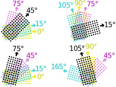
I use the following orientations for my patterns.
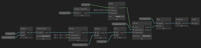
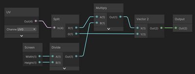
Jump to heading Screen-space UVs
In my graph, I also used the following nodes as the UV input for the dots pattern subgraph so that I could apply the halftone shader as an image effect for the whole screen.
Jump to heading Download
The shader can be downloaded below as a Unity package.
Jump to heading Additional resources
(1) https://en.wikipedia.org/wiki/Halftone